Raster Design Rubber Sheet

Part of the cad masters books instructional series.
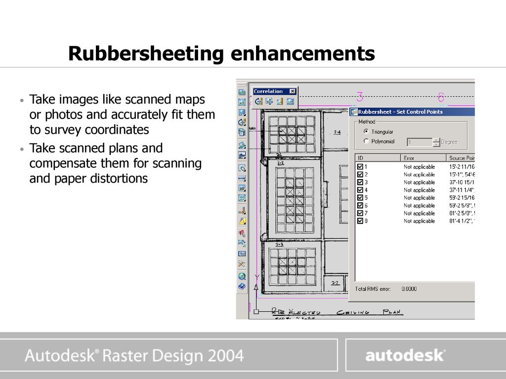
Raster design rubber sheet. Where applicable you can see country specific product information offers and pricing. See my previous post on raster design for more details about fixing image skew. You may notice some of the drawing was fixed but there are other places in the drawing that are not orthogonal. The autocad raster design toolset helps you convert raster images into dwg objects with its powerful vectorization tools.
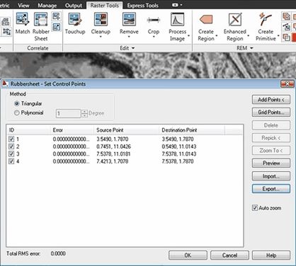
You must select at least three pairs of source points and destination points. Go back to my second post to see how the rubber sheet can help you with this. You have been detected as being from. When i rubbersheet i always anchor the two known points that i matched the image too and then i anchor all 4 corners of the image.
Conflation applications use rubbersheeting to align layers in preparation for transferring attributes. Rubbersheeting is commonly used after a transformation to further refine the accuracy of the features to an existing layer or raster dataset. Cad masters tutorial on using the rubber sheet tool in raster design. Choose rubber sheet from the raster tools ribbon tab and select the polynomial option.
I m assuming you are using raster design. The convex hull of destination points is displayed in red while the convex hull of source points is shown in blue. Rubber sheet command step 2 the first point you click will be where the image file is off. The anchors at the four comers really help.
Select the first source point for the first control point on the image. מוצגת כאן הפעולה אשר מותחת ממקמת ומשנה את התמונה לפי נקודות. Below is a picture of my rubber stamp points for this. The rubbersheet dialog box disappears and autocad raster design toolset prompts you to select the first source point.
זהו סרטון המציג את יכולות התוכנה לעיגון תמונה. Then choose add points and start clicking on the drawing. After the anchors are set i will define the stretch points.


